Design assistance tools
The software provides several design assistance tools to make drawing activity areas and division lines more accurate and efficient. These tools help you control geometry (such as by drawing lines with precise angles and distances), measure features, and maintain precision during the design process.
The tools include:
-
Bullseye cursor: Displays concentric rings around the cursor to help with spatial alignment.
-
Feature measurements: Shows angles and distances between vertices for precise geometry.
-
Input restriction: Limits the length and/or bearing of a segment during drawing.
Bullseye cursor
The bullseye cursor provides a visual reference for distance when placing points. It displays concentric rings at set intervals from the cursor, helping you maintain consistent spacing. You can switch on and off the cursor at any time with a keyboard shortcut – and configure its visual settings.
Turning on the bullseye cursor to align a new point with an existing activity area point
You can customise the cursor, showing any number of rings with a certain radius and colour.
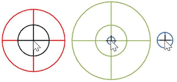
Different bullseye cursor styles
Show the bullseye cursor
You can toggle the bullseye cursor and configure its visual settings.
-
Enable or disable:
Toggle the bullseye cursor using the C key or by clicking the cursor icon
 in the toolbar.
 -
Configure settings:
Go to Graphics Settings
 > Cursor to adjust ring spacing and style.
Feature measurements
Feature measurements display real-time angles and distances between vertices as you draw or edit an activity area. This helps ensure accurate geometry, especially when aligning with design constraints.
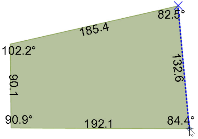
Drawing an activity area while showing its measurements
Show feature measurements
You can toggle the feature measurements and configure its visual settings.
-
Enable or disable:
Press M to toggle measurements on or off for the selected area.
Labels must be enabled in the graphic settings (see the point below).
-
Configure style:
Adjust size and colour in Graphics Settings
> Annotations.
Input restriction
Input restrictions allow you to control the geometry of each segment—of editing an activity area or drawing a division line—by setting:
-
Length: Fix the segment to a specific distance.
-
Bearing: Lock the segment to a specific angle (clockwise from north).
-
Both: Apply both length and bearing constraints.
Input restrictions ensure each new segment adheres to the specified length and/or bearing, making it easier to follow engineering tolerances or design guidelines. The same restrictions apply to the divide line, allowing you to split areas along precise angles or distances. This is particularly useful for creating clean, consistent boundaries.
An animation of creating division lines using bearing and distance locks. Wirth these restrictions, the large activity area can be cut into grids of equal sizes.
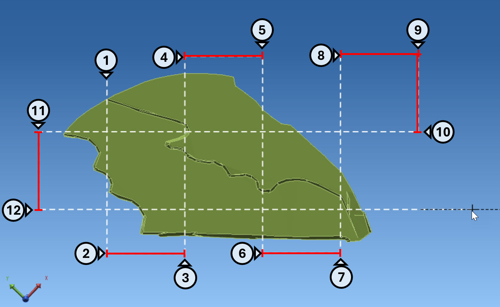
A still view of the division lines, formed using the input restrictions
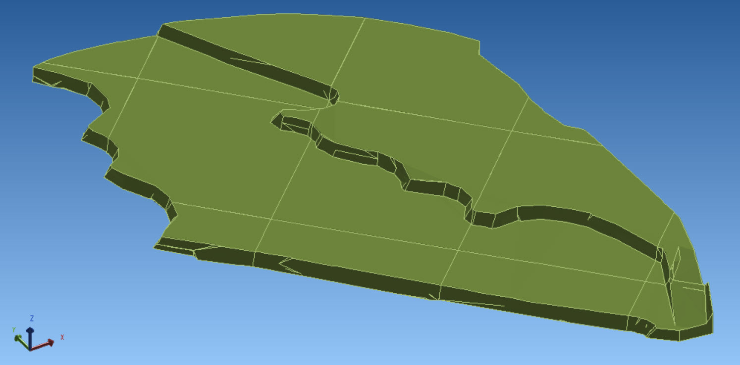
The result of dividing the large activity area into grid-based activity areas
The current restriction mode appears in the status bar as NONE, DIST, BEAR, or BOTH.
Use input restrictions
-
Enable or edit restrictions:
Press L to open the input restriction settings and apply the desired values.